|
The Simplified School Girl (SSG) Project
Schematic | Parts Kit | Introduction | Instructions | Materials | Parts Sources | Tools | Construction | Avoid | Safety | Group Tests | Resources for History, Theory, Advancement and Application
To join the advanced Yahoo Bedini_Monopole groups you must first build a Bedini Monopole Energizer and test it according to the information given. Additional construction details are found here: http://peswiki.com/index.php/Directory:Bedini_SG You must provide your real and full name and provide data showing you have done the basic load tests mentioned on the following beginner's group: Yahoo Bedini_Monopole3. If you cannot build according to the plans we cannot help you do that. Please do not ask questions about electronics. This list is for those who are willing to actively participate in doing simple testing of this Energizer.
Absolutely no questions about the advanced groups will be read and answered without people first building, testing, and providing test data to the following email address:
Bedini_Monopole3-owner@yahoogroups.com
|
Basic Schematic
|
Introduction to John Bedini Monopole Mechanical Oscillator Radiant Energizer Simplified School Girl (SSG) Project
Summary Statement:
What I Understand the SSG to Be:
Mental Preparation Necessary to Learn:
Twofold Purpose of this Experiment:
Commitment to the Policy:
The Quest for Free Energy or Over Unity:
Instructions
Low Resolution Video for dialup:
84MB wmv edition |
|
Materials List
The following is a list of materials that may be necessary to replicate the Bedini School Girl circuit and motor as presented in this guide. Some of the parts are flexible. Alligator Clips · Specifications
Batteries, Rechargeable Lead Acid, deep cell (like Golf cart 6v or 8v preferred). But you can use car batteries or small 1 to 12 ah lead acid or gel. Bicycle Wheel Rim -- Or Other Rotor Device Non-magnetic wheel rim
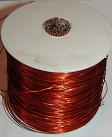
Coil Spool · Purpose
· Specifications
· Tolerance
· Sourcing
PO Box 1246; Pittsfield, MA 01202 Tel: (413) 442 - 0067; Fax: (413) 445 -7849 E-mail info@pittsplas.com Diode (D1) · Specifications
· Parameters
· Sourcing
· Estimated cost
Diode, 1000 Volt (D2) · Specifications
· Sourcing
· Estimated cost
Magnet Core (Welding Rod) · Specifications
· Quantity
· Tolerances
· Sourcing
· Estimated Price
Magnet Wire for Coil Winding · Specifications
· Tolerance
· Quantity
· Sourcing
· Resources
Magnet Wire for Trigger Coil Winding · Specifications
· Tolerance
Magnets · Specifications
· Quantity
· Tolerance
· Source
Neon Lamps · Purpose
· Specifications
· Quantity
· Make & Model
· Source
· Estimated Price
Resistor · Purpose
· Specifications
· Tolerance
· Sourcing
· Estimated Price
Super Glue Tape · Purpose
· Tolerances
Transistor · Specifications
· Quantity
· Sourcing
· Estimated Cost
Wood (Stand) · Purpose
· Specifications
· Quantity
· Tolerance
· Sourcing
· Estimated Price
Tools Needed · Wire cutter. · Something to cut the welding rods to length (may want to use cutter available where you purchased the rods). · Something to fabricate the stand for the wheel. (e.g. jig saw to cut wood). · Soldering gun and solder. · Metal drill to put hole in aluminum heat sink to fasten circuit to device. · Screw driver and 2-4 screws to screw heat sink to stand. · Skill Saw, to cut boards. · Drill, to wind wires on coil. Digital voltmeter, analogue ampere meter. Oscilloscope is needed for more advanced testing. Contacts
|
Parts Sources (US and International)
Tools
Construction
Avoid
Safety
SIMPLE GROUP EXPERIMENT TO SHOW TWO ENERGIES USED IN BEDINI MONOPOLES. Refined instructions are forthcoming. See http://groups.yahoo.com/group/Bedini_Monopole3 for details.
A set of instructions is given below for three simple steps. This is where everyone should start with learning about these machines. As you will see in the instructions, you are not to assume anything or change anything. No need to do anything but the simple SSG setup. No upgrades needed. No need to worry about a perfect setup. We are looking to see what happens to the charging battery. What is the difference between what the meter says goes into it, and what kind of work we can get out of that battery on a repeated basis. Do as many presentations as you wish to help in this project. Below the specific instructions are misc. coaching instructions you will want to pay attention to. Each set of instructions follows the posting where it was found on the main list. Further clarifying remarks between these [ ] brackets may be added later.
STEP BY STEP INSTRUCTIONS:
From http://groups.yahoo.com/group/Bedini_Monopole/message/2868
1. Take a small, 1 coil, smooth running, SSG. No capacitor dump [setup], just take the diode output of the coil and put it to a secondary battery positive [that is the SSG setup with the diode and not the SCR]. The secondary negative terminal should be hooked to the primary positive. Set it to where the mechanical efficiency of the motor peaks out at 75ma input current or below. [If you cannot build that small of a machine, then report your results with higher draws.] The way I tune this is to measure the ratio of rpm and convert to magnets/minute then divide by the ma. You'll have to have a tachometer, or count scope traces to get your mpms. [Or use a meter that measures Hertz] Measure your input current with both your analog meter and your digital meter, and note any major discrepancies. If there is, report the measurement from your analog meter. From http://groups.yahoo.com/group/Bedini_Monopole/message/2880
Step 2
Now that we have optimized motor output, the next step is to measure the current going into the output battery. At this point we will not be concerned with the current being used by the input battery. This will come into play later; so for now, as hard as it is, just forget it. Now everyone who has played with this circuit knows that measuring the pulsed dc current is a little trickier than normal. I try to measure it with at least two different methods until I can get the two to agree with one another. Then I know that I am close. Here are the two easiest ways I have found to measure this energy.
#1) The easiest. Get yourself an ANALOG current meter and put it in series with the 2ndary battery. Measure the voltage of the secondary battery. Multiply the two together to get the watts.
#2) Get 2 identical small flashlight bulbs (12v 100ma for example). Replace the secondary battery with one of the light bulbs. Run the motor. Now take the other light bulb and put it in series with a potentiometer and a current meter. Hook it to the same battery you are running the motor on. Adjust the potentiometer until both light bulbs glow at the same brilliance. Then read the ampmeter. Put an voltmeter across the lightbulb. Multiply the volts times amps to get the watts.
From http://groups.yahoo.com/group/Bedini_Monopole/message/2899
Step #3) Stop the motor. Take your secondary battery out of the circuit and put a known load across it (I like to use a 10watt 10 ohm, for example [that is too high for really small batteries which could use a higher ohm resistor like 50 ohm more or less). Get a stopwatch and measure, as precisely as you can, the time you are discharging the battery. Put a digital volt meter across the resistor and note the voltage levels during the discharge time. You will be needing to get an approximate average voltage across the load resistor during this time. You want to take the voltage down to a predetermined voltage level which you will be watching precisely say 12.40V for example. When it gets close to this level (12.41 in this case) disconnect the load from the battery and stop the stopwatch as soon as the meter first flashes 12.40. We are going to call this, for future simplicity's sake, the load termination point. Now measure the power in joules (or watt-sec) that you took out of the secondary battery. Multiply the duration of the load from the stopwatch (in seconds) * AVERAGE voltage * AVERAGE voltage / the resistance of the load (in ohms). This will give you the output of the system in joules. Write this down.
Now, take the battery and put it back in the charge circuit in the SSG and run the motor for an hour. Set a timer and run the motor charging the battery back for precisely an hour (3600 sec). (If the battery tops out before this just shorten the duration but make it constant.) Multiply your input energy figured in step 2 (watts) times 3600 (or your arbitrarily decided charge time) and you will have your input power in joules. Write this down.
Repeat this experiment at least 5 times in a row or until you can get consistent input and output measurements. The amount of power you can take out will reduce significantly the first few times until it stabilizes. When you do the experiment twice in a row and get the same results you will know that your particular system has stabilized and you can get an exact figure of the cop on the back end.
MISC. INSTRUCTIONS. http://groups.yahoo.com/group/Bedini_Monopole/message/2882 The data from this experiment will be continually posted under the database section of this group. I am encouraging everyone to CONTINUE to see this experiment through if you have begun it, even if you want to change things after viewing everyone else's numbers. If you want to change your setup, do it AFTER this experiment and report your findings. We will add another column for your next setup. This is not a competition, it is mass experimentation for the learning benefit of all involved. The data from those who have extreme numbers, even on the low side, is important. Everyone needs to learn what to do and (as equally important) what not to do. http://groups.yahoo.com/group/Bedini_Monopole/message/2888 If you want in the experiment, forget the conditioning for now. Just put one battery on the back end and one on the front. The wall charger is fine. Don't worry now about matching to the c20 rate of the primary, just find the sweet spot of the motor, the most magnets per minute per miliamp wherever that may be. Just report your measurements for steps 1 and 2. http://groups.yahoo.com/group/Bedini_Monopole/message/2889 --------------Don't cheap out on the 2ndary battery if you are efficiency testing.-----------------
You will be disappointed and all your efforts will be in vain. Yes, this circuit can desulphate old batteries, but it can't put electrolyte back in dried up gel cells, and it can't straighten warped plates, and it can't repair shorted cells.
The better shape the back battery is the better it will take the charge and that's the ONLY thing we are after in this experiment.
I bought loads of batteries at "great deals" only to find that they must have sat on the shelf for too long and could only be charged to 50-75% of their rated capacity.
If you want to do multiple setups that's fine, just report each separately and we'll log the data accordingly.
http://groups.yahoo.com/group/Bedini_Monopole/message/2911 One point for future consideration. I would not get in the habit of taking the battery down to 12.00V. It will shorten the battery's life considerably if this is habitually done. I would work between say the 12.4V and 13.0V range [12.40 and 12.70 is ideal for efficiency tests.]. By all means, don't let it set for days uncharged. http://groups.yahoo.com/group/Bedini_Monopole/message/2923 The simple reason being that the secondary battery is a lot lower in impedance than your 10ohm load, so it will naturally pull more power. Granted, it can't take the whole power pulse, as the bottom 24V of it is not great enough to push through the secondary, but none the less, it consumes more power than your 10ohm load resistor, (not to mention has much more smoothing action than your capacitor). http://groups.yahoo.com/group/Bedini_Monopole/message/2924 If you wanted to adjust to the C20 rate, you could. The battery would have less "bounce". But that is about the only difference. It is true, for longer durations, and for a little more accurate results, you could go for the c20 rate. Your battery would not heat up as much in discharging. But the 10ohm resistor for this test, will expedite the load testing, and will not throw the results off significantly. http://groups.yahoo.com/group/Bedini_Monopole/message/2927 I agree that the one spike vs. many spikes needs to be investigated further. However, I don't believe John has said anywhere to limit this to 1 spike. I'll tell you that in some of my setups, one spike per pulse worked the best, others liked multiple spikes per pulse. We are not looking for specific waveforms. We are looking for arbitrary data which shows maximum efficiency. http://groups.yahoo.com/group/Bedini_Monopole/message/2935 I know the temptation is very strong to jump forward into another experiment, and I expect that everyone will want to try different things. That is to be expected and encouraged. But I am suggesting to all, at this point, to maximize all their efforts in getting the best possible numbers for steps 1, 2, and 3. There has been an overabundance of speculation and presupposition on these groups that tend to drown out the results of successful scientific experimentation.
I would really like to see this forum transform from a group of Bedini enthusiasts to a fast-growing consensus of researchers with documented proof of the legitimacy of this technology.
Resources for History, Theory, Advancement and Application.
John Bedini's book, a few of his DVDs and an SSG parts kit: rpmgt.org/order.html The following is the Yahoo forum we are using to discuss and build these machines: http://groups.yahoo.com/group/Bedini_Monopole3Some of the plans for building this device come from the following web site: http://peswiki.com/index.php/Directory:Bedini_SG The theory and information behind this are found at the following webs sites: US Patents 7,109,671 6,545,444.
Bedini websites: icehouse.net/John1 | icehouse.net/John34 | Energenx Products
energenx.com/john1/index001.html, energenx.com/john1/intro.html,
energenx.com/john1/john1.html Thomas Bearden: cheniere.org
Transcribed Tesla Patents
588177 APPARATUS FOR PRODUCING OZONE highlighted Some Tesla's patents relating to Bedini SSG
Patents 512340 593138 685012
|