Simplified School Girl (SSG) Presentation
"Unidirectional Wave Impulses"
The copyrighted video presentation may be freely distributed provided that nothing is altered,
deleted from it or added to it. This video is for educational and entertainment purposes only.
Replicate at your own risk. We assume no responsibility for anyone replicating anything shown here.
|
Pictures | Video | RPM & AMPS | Charging Rate | Compare with Other Chargers | Models with Fans | Benefits | Parts Kit | Fakes | Response to Skeptics | Tesla | Old SSG pages | Your Comments
Welcome to this demonstration of Monopole Mechanical Oscillator Energizer. This presentation is primarily for the internet Yahoo groups public forum called DualPole Motor Generators where I am teaching people how to build and test this simple patented motor-Energizer. Everyone is welcome to learn. Here is a page in progress about instruction details:
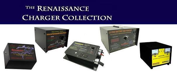
Now selling Solid State Battery Renaissance Chargers
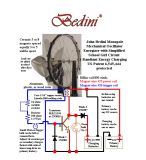
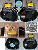
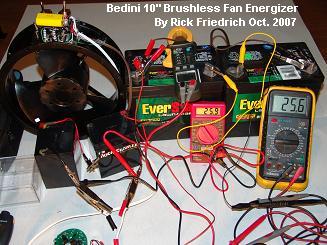
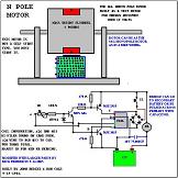
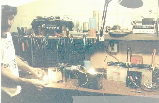
Some pictures from the video: Click image for larger photos. A shot of setup, materials, and testing equipment.
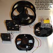
OTHER MODELS SHOWN WITH FANS
Some other SSG Energizers made with conventional brushless motors shown in video.
FOR ALL VIDEOS SEE RickFriedrich on Youtube here
RPM & AMPERE DRAW
I set it to where the mechanical efficiency of the energizer gives me the ratio of the lowest ampere draw on the primary battery to the fastest speed (or more importantly to the highest charging rate in the charging battery). This may take a little playing around with, but do not worry about perfect results to start with. I start with 680 ohms resistance on the trigger resistors and work up or down from there. Lowest setting for this 16 Pole SSG was set at highest (using an 800 ohm pot.) trigger resistance (900 ohms plus 25ma bulb) 25" rotor, 16 magnets, bifilar coil 790 winds #26 & #23
27 milliseconds per magnet
Ampere Draw on Primary Battery
0.120 Amperes * 12.33 Volt battery = 1.48 Watts
CHARGING RATE MEASURED It is not recommended to leave any meters hooked up to the charging battery or in series with the paths to and from it. The meters will become part of the circuit and negatively affect the charging rates. Therefore only momentarily place the meters across the charging battery or in series with it.
Voltage across charging battery was 12.56 So if the charging battery charges at the rate of discharge of the primary battery, then we have to figure out where this extra 1 Watt is coming from, or we have to abandon our meters in relation to this technology. The 1 ohm resistor test shows that no significant current flow is crossing the path of the charging battery. The voltage and amperage test above shows that when the battery is connected, the meter shows more apparent current flow when the battery has a lower impedance than 1 ohms. But the current meter shows much less than the primary draw to run the circuit and loads. I have run numerous tests with this circuit and various modifications to verify that the charging battery charges at a rate equal to 80% to 95+% (depending on how well made) of the discharge rate of the equal size primary battery. If the charged battery is loaded down properly we can compare the two loads in the different batteries to figure out work done. I have also seen that whatever way we measure the current going into the charging battery, we should see more work being done by that battery under load with repeated cycles. When we run sufficient load comparrison tests, calculate the losses in the circuit (transistor, resistors, diodes) in heat, the work done in light in the bulb, and the mechanical work done with the wheel, we can very easily see that we are getting more out of the SSG Energizer than what we are putting into the system with our primary battery. The mechanical output can easily more than make up any of the 20 to 5% difference. And adding more batteries to the charging bank will increase the amount of work able to be done with that bank. The efficiency of the circuit and motor is not the same as the COP. The efficiency is less than 100% while the COP is greater than 1. The energy transfered for work by the primary battery has an efficiency of less than 100% as there are losses mentioned. But the resulting useful work out of the system can be greater than what that primary battery supplied. This is analagous to a wind, solar, or hydro generation system where the opperator provides little or no collector current to tap a free environmental energy source. In this case the battery is being uniquely triggered to charge itself.
COMPARRISON WITH OTHER CHARGERS Running the same sort of tests with other chargers will reveal a gradual loss of load time after each charge cycle. With the SSG Energizer we have seen increases. We have also seen old batteries that could no longer take a charge come back to life again. See Bedini Product Chargers: Renaissance Charge LLC
A more efficient charge controller for DC converters. Free mechanical energy of whatever power needs. Cooler switching and charging temperatures. The circuit is not closing the loop constantly; It reduces the BEMF by charging another battery or load. Can be made to any size.
Very low res. 7MB video of the 6" fan running. Better quality video of this. Overview and conversion of the fan is shown in a video with WMV format that will be sent on a CD (with pictures and other video) with the kit: This is the lower quality Google video. This is a little higher quality.
Beware of Fake MJL21194 Transistors.
We thought we were saving money buying Ebay and elsewhere.
http://rpmgt.org/Fake/1.JPG | http://rpmgt.org/Fake/2.JPG
Transcribed Tesla Patents
588177 APPARATUS FOR PRODUCING OZONE highlighted This patent shows you some similar processes.
A few more of Tesla's patents relating to Energizers
Select Tesla Publications
Old SSG Pages
JohnBedini.html
|
